메시지를 남겨주세요
저희 제품에 관심이 있으시고 더 자세한 정보를 원하시면 여기에 메시지를 남겨주세요. 최대한 빨리 답변드리겠습니다.
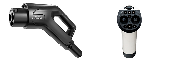
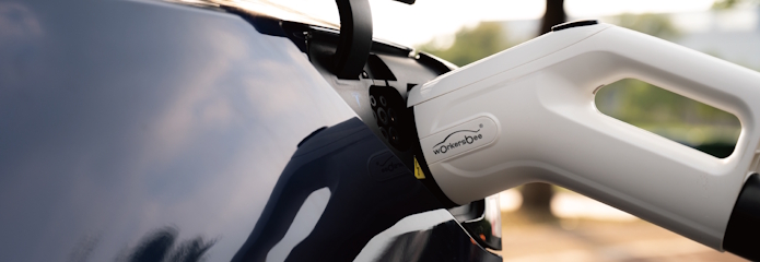
| 프로젝트 유형 | 제품 방향 | 주요 선정 요소 | 준비해야 할 정보 |
|---|---|---|---|
| 저전력 DC 충전 장비 | G3.0 저전력 DC 커넥터 | 20~80A, 750/1000V DC, 케이블 크기 및 취급 | 정격 전류 및 전압, 케이블 길이, 충전기 측 단자 |
| DC 고속 충전 장비 | G4.0 자연 냉각식 또는 액체 냉각식 DC 커넥터 | 80~350A 또는 400A/600A 최대 전류 구성, 케이블 직경, 냉각 시스템 요구 사항 | 필요한 전류 프로파일, 전압, 냉각 구조, 케이블 길이, 작동 조건 |
| AC 충전 장비 | G1.0 AC 커넥터 | 16A 또는 32A, 단상 또는 삼상, 250/440V 교류 | 위상, 전류, 전압, 케이블 길이, 충전기 측 배선 |
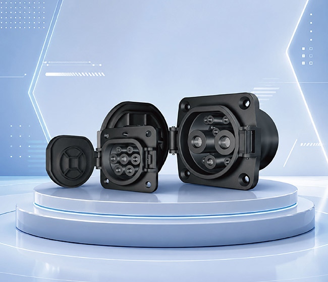
| 차량 측 DC 인터페이스 | GB/T DC 차량용 입력 단자 | 80~250A, 750/1000V DC, 장착 공간 및 케이블 배선 | 차량 플랫폼 등급, 설치 도면, 사용 가능 공간, 케이블 종단 처리 |
| 차량 측 AC 인터페이스 | GB/T AC 차량 흡입구 | 16A 또는 32A, 단상 또는 삼상, 250/480V 교류 | 위상, 전류, 전압, 설치 도면, 케이블 배선 |
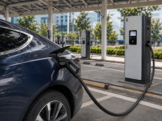
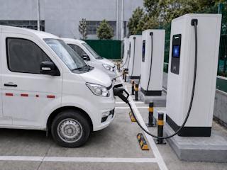
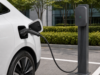
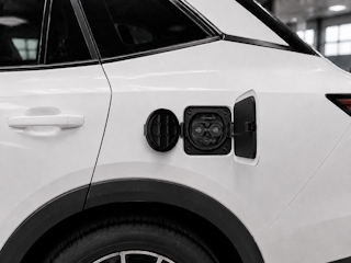


현재 GB/T 커넥터 및 차량용 입력 단자 사양에는 IP55 보호 등급, -30°C ~ +50°C의 작동 온도 범위, UL94 V-0 하우징 재질 성능, 그리고 10,000회 이상의 결합 주기에 대한 기계적 수명이 명시되어 있습니다. 이러한 등급은 현재 G3.0 및 G4.0 DC 커넥터, G1.0 AC 커넥터, 그리고 AC/DC 차량용 입력 단자 제품군에 적용됩니다. 적용 가능한 보호 조건 및 최종 구성은 선택한 모델, 설치 방법 및 작동 환경에 따라 반드시 확인해야 합니다.
커넥터 구성은 충전기의 전류 프로파일 및 냉각 구조와 일치해야 합니다. 주요 매개변수에는 냉각 매체, 유량, 작동 압력, 케이블 길이, 냉각수 용량 및 충전기 측 냉각 연결부가 포함됩니다. G4.0은 물-글리콜 또는 실리콘-오일 구성을 지원하며, 기준 냉각수 유량은 1.5~3L/min이고 압력은 약 3.5~8bar입니다. 최종 시스템 매개변수는 선택한 최대 전류 400A 또는 600A 구성에 대해 확인해야 합니다.
프로젝트 기반 옵션을 통해 케이블 길이 및 후단 처리(충전기 측 종단 처리 요구 사항 포함)를 선택할 수 있습니다. 필요한 전류, 전압, 케이블 길이, 피복 제거 치수, 단자 요구 사항 및 충전기 측 배선 세부 정보를 제공해 주십시오. 최종 케이블 조립은 선택하신 제품 구성 및 작동 조건에 따라 엔지니어링 승인을 거쳐 확정됩니다.
표준 차량 흡기 매니폴드 어셈블리는 흡기 매니폴드, 보호 커버, 케이블 어셈블리, 전자 잠금 장치 및 온도 센서로 구성됩니다. 케이블 끝단 처리는 차량 측 연결 요구 사항에 따라 구성됩니다. 프로젝트 확정을 위해 필요한 AC 또는 DC 구성, 전류, 전압, 해당되는 경우 위상, 케이블 길이, 설치 도면, 케이블 배선 경로 및 끝단 피복 제거 또는 단자 요구 사항을 제공해 주십시오. 최종 조립품은 차량 플랫폼 및 설치 배치도를 기준으로 확정됩니다.
메시지를 남겨주세요
Wechat으로 스캔 :

WhatsApp으로 스캔 :





 한국어
한국어